

Vibration switches calibration
Operating principle
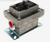
The Vibration switch (figure in the next page) is sensitive to vibration in a direction (the sensitive axis) perpendicular to its mounting base. It contains a vibration detecting mechanism, which also functions as a “mechanical amplifier”.
To activate a snap-action switch when the selected level of vibration is exceeded and the detecting mechanism “trips”. The detecting mechanism consists of an armature suspended on a flexure pivot-which is restrained from motion by a permanent magnet (the hold-down magnet).
In the “armed” condition, the armature is held against the stop pin by the hold-down magnet. The stop pin maintains a precise air gap between the armature and the hold-down magnet. On the opposite end of the armature, the compression spring provides an adjustable force to oppose the force of the hold-down magnet. Whenever the peak vibration inertial force (mass X acceleration) plus the adjustable compression spring force exceeds the force of the holding magnet, the armature is released and is pulled into the latching magnet “Tripped” position.
Simultaneously, it activates the snap-action switch. This detecting mechanism has a uniform response from 0 to 300 Hz over a range of 0 to 4.5 g’s.
The mechanism may be reset to the “armed” position manually (locally) or electrically (remotely).
Manually, depress the reset button to move the armature away from the latching magnet “Tripped” position until it is held against the stop pin “Armed” position. Electrically, the rest coil may be activated to pull the armature into the “armed” position against the stop pin.
A reset and holding coil is provided, in the DC/AC voltage as specified, so that accidental shutdown on starts can be prevented. External time delay relay circuits are required to maintain voltage at the holding coil during the start-up period and then release this voltage when operation is normal.
At full voltage, the reset coil should not be energised for more than four minutes to prevent overheating. Then the reset coil must be de-energised for a period of 10 minutes before re-energising. For longer hold-in requirements the reset coil should be energised at full voltage and then held-in at one-half the rated voltage.
Vibration Switch mounting
The vibration sensitive axis of the vibration switch is perpendicular to its mounting base. Therefore, the vibration switch must be mounted in a plane that will detect the vibratory motion for which protection is desired. The vibration switch may be mounted at any location along the length of machines containing rotating shafts that are horizontal and parallel to the base of the machine: Figure (in the next page) shows the preferable location being in line with the rotating shaft. Vibration switch not mounts perpendicular to the ends of rotating shafts unless the endplay or end-thrust measurement is desired. Normally, bent shafts unba1ances on the rotating mass of the shaft, worn bearings, and other anomalies are detected near the bearing housings and at right angles to the shaft.
The vibration switch may be mounted in any position between the side (vertical) or the top (horizontal) of bearings or machine housings. It should be noted that when mounting Vibration switches on top (horizontal position) of equipment the vibration measurement range is as stated in the Specification.
If a mounting bracket assembly is used to mount the vibration switch due to an irregular mounting surface, it must be constructed of steel having sufficient thickness and properly reinforced so that mechanical resonance’s are not introduced. Usually 1/2" steel plate is satisfactory if the dimensions of the bracket are minimal. It is extremely important that all Four Corners of the vibration switch, as well as the mounting assembly, be rigidly secured to the machine. Exact location is not critical as the adjustment procedure of the vibration switch automatically accounts for the normal vibration at that location.