


3300 Dual Vibration and Gap Monitors
Shaft radial vibration amplitude and radial position are primary indicators of the overall mechanical condition of rotating machinery. Many machine malfunctions, including rotor unbalance, misalignment, bearing wear, shaft cracks and rubs, can be detected with one of these measurements.
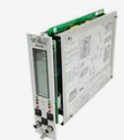
The 3300 Vibration Monitor has two channels. Channels A and B operate the same, but provide information from two points on the machine. This vastly increases the information available and makes advanced diagnostics possible.
2. The OK LED’s are illuminated when tile channel is monitoring properly. If e1tller OK is extinguished and RESET does not bring it back, notify instrument technicians immediately. The OK's indicate that a monitor is operating correctly.
3. The Alert LED is illuminated when tile first level of alarm is exceeded. Each channel has an Alert alarm. Once a machine's vibration has decreased below tile alarm level, the LED can be cleared by pressing RESET. Pressing tile ALERT switch displays the current alarm setting.
4. Pressing the DANGER switch will cause the display to indicate where the Danger Setpoints for both channels are located. Some monitoring systems that are configured to shut down a machine may have a special option activated. This is the danger voting option. Depending on how it is optioned, it could mean; I.) Both channels must exceed their Danger Alarm Setpoints before a shutdown will occur, OR 2.) Only one channel must exceed the Danger Alarm Setpoint to cause a shutdown.
5. Pressing the GAP switch gives the Gap Voltage values for both channels and is read off the centre scale (6.) in volt dc. Not all monitors have this switch. The GAP switch provides information that is related to a certain type of transducer. This switch does not affect monitoring in any way when actuated and can provide valuable information.
6. The centre scale is associated with monitors having a GAP Switch (see 5. above). The meter indication is read off this scale when the GAP switch is pressed. The 3300/16 monitor has a special option that has the ability to alarm on a shift in gap. If this feature is enabled, the monitor will display the Gap Alarm setpoint referenced to the centre scale when the ALERT and GAP switch are pressed simultaneously.
7. The right side of the scale corresponds to the B channel. All measurements for the channel (vibration, alarm setpoints, gap) are read off this side.
8. Same function as 3, except this indicates the Danger (trip) or second level of alarm.
9. On all monitors each channel has a Bypass LED or Indication that is normally extinguished. When one or more of these lights are on, part or the entire monitor, is not functioning. Check with the instrument technicians if in doubt.
10. When used alone, this switch will cause the first level of alarm to be displayed for both channels. If being used with a vibration monitor equipped with an enabled Gap Alarm, it will display the Gap Alarm setpoint if Gap is pressed simultaneously with Alert.
11. Diagnostics engineers and instrument technicians use the Buffered Transducer outputs. This bypasses the monitoring system and does not affect meter indications.