Flow Cup Calibration and Viscosity Cups calibration procedure
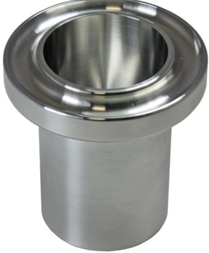
The viscosity of a Non-Newtonian fluid is commonly measured using flow cups, viscosity flow cups, and viscosity dip cups. These devices require routine calibration to ensure accurate results, and even new ones should be calibrated to prevent manufacturing faults or errors. Flow cups are designed from a solid billet of aluminum with a hollow central portion that holds the fluid under test, a high precision nozzle controlling the flow, and a gutter to catch excess fluid.
Dip cups have a similar design but do not have a gutter, while Zahn Dip Cups are made from stainless steel. Both types have a long handle, a precision nozzle, and a hollow central cylinder that contains the fluid being tested. Types of flow and dip cups include BS 3900, ISO 2431, Ford ASTM D1200, DIN 53221, AFNOR, Shell, Fririkmar Dip Cups, and Zahn Dip Cups.
Procedures for Flow Cup Calibration / Viscosity Cup Calibrations include a certified reference oil of appropriate viscosity, a calibrated reference thermometer with an accuracy of greater than 0.1°C, a calibrated stopwatch, a stand for flow cups, a level for levelling the cup, and a water bath or formula to correct reference oil for temperature.
Calibration procedure for viscosity flow cups
Level stand.
Visually inspect the flow cup for damage or contamination, clean if required.
Ensure flow cup and reference oil is at the required temperature, usually 20°C or 25°C.
Place finger over the nozzle.
Fill with oil while ensuring no air bubbles are present, it should be slightly overfilled.
Using a glass plate, slide carefully across the top of the cup to remove the excess oil into the gutter.
Remove finger from the nozzle.
Simultaneously remove the glass plate horizontally and start the stopwatch.
Stop the stopwatch precisely the moment you see a break in the flow. This is called the efflux time and should be taken note of.
Following the relevant ISO, DIN, ASTM or other standard, ensure that the expected efflux time and observed efflux time are within the specification stated.
Repeat steps 3 to 9, three times and calculate the mean time. If any times are greater than 0.5 seconds apart, repeat this timing until you have three satisfactory results.
The calibration procedure for viscosity flow cups involves visually inspecting the flow cup for damage or contamination, ensuring it is at the required temperature, filling the cup with oil, removing excess oil, starting the stopwatch, stopping the stopwatch when there is a break in the flow, and repeating steps 3 to 9 three times to calculate the mean time.