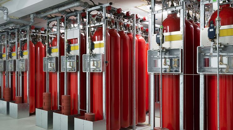
FIRE & GAS SYSTEM

FIRE & GAS SYSTEM

the Fire and Gas system (FGC) is designed to provide the earliest possible warning and location of fires in their initial stages, flammable gas leakage or accumulation up to the lower explosive limit (LEL%), and any toxic gas likely to be present up to the occupational exposure limit (OEL). The system includes detectors such as manual call points, fire detectors, or toxic gas detectors, which interface with the Fire & Gas control panel (F&GCP) through detector interface modules.

The F&GCP acts on information from a certain number of inputs that agree, known as a 'voting' system. Output interface modules receive outputs from the processing unit and provide to output circuits (Relays), providing electrical isolation between the plant and F&GCP and providing the required power for operation. Output devices can be alarms (audible/optical) and/or control circuits.

Protected plants are typically divided into fire areas, each with its own detection, alarm, control, and extinguishing system. If both fire and gas detection are required, these systems share common control panels. The fire detection and alarm system has manually operated call points and automatic smoke, heat, and flame detectors located in areas where a fire hazard may exist.

The type of a Fire & Gas control panel and associated detectors/outputs depends on the type of controller it self. Addressable type systems have addressable detectors individually identified at the F&GCP via a data highway, while traditional type systems have detectors that change the value of the electrical current in its loop via normal wiring connections.

Manual call points (MACs) initiate visual and audible warnings in the plant, while automatic alarm call points (AACs) are installed at strategic locations within process areas or buildings.

Smoke detectors are essential in confined areas where smoke can be easily detected. They are mixed zoned types, usually one is an ionisation type and the other is a photoelectric type. Ionization smoke detectors are sensitive to visible and invisible smoke particles produced during the incipient stages of a developing fire and are suitable for use as early warning fire detectors in various industrial, commercial, and residential applications

The detector contains an ionisation chamber consisting of a small Americium 241 radioactive source mounted between two metal electrodes. The alpha particles emitted by the americium ionise the air into positive and negative ions, which separate and travel to electrodes of opposite sign. Some ions collide and recombine, but the net result is the flow of a small electrical current between the electrodes. When smoke particles enter the chamber, ions become attached to them, increasing the rate of ion recombination and reducing the chamber current. This reduction in current can be used to monitor smoke concentration.


The detector is typically connected to a central control unit providing a two wire monitored supply of between 17 volts and 28 volts d.c. Terminals 1 and 6 are provided for the connection of the incoming positive and negative supplies respectively. Terminals 2 and 5 are connected to terminals 1 and 6 by tracks on the detector's printed circuit board, allowing continuity monitoring of both the positive and negative supplies through the detector.

Photoelectric "optical" smoke detectors consist of a detector head and base, with the head being a solid-state device with a high reliability light sensor and pulse signal processor (LED). The base contains an LED for alarm verification, screw terminals, and bifurcated contacts. The detector head twist locks into the base and is secured by a special locking screw.

The Photoelectric Smoke Detector incorporates the light scattering principle within its solid-state sensing chamber, allowing the detector to sample optimum products of combustion (smoke) entering from any direction while rejecting ambient light levels.